company tower banner
SABIC's Specialties Business Company Logo

ULTEM™ Resin

SABIC's Specialties Business Brand

Discover range of PEI resins - ULTEM™ resins – amorphous, transparent, polyetherimide starting with ULTEM™ 1000 unreinforced PEI resins, high-performance base material for blends, reinforced grades, offering: long-term high heat capability, dimensional stability, strength and modulus, inherent low FST, non-halogenated FR solution, hydrolytic and chemical stability, IR transparency, stable dielectric properties, lightweight, colorability.

ULTEM™ HU1004 resin, PEI resin blend, healthcare grade well suited for strong, durable medical devices that withstand multiple sterilization methods, offer enhanced hydrolytic stability in steam autoclave sterilization. ULTEM™ 9085 resin, a PEI resin blend, offers robust OSU/FST properties, meets FAA requirements, and may be used in impact-resistant aerospace interior parts, ground transport applications, pellet-fed additive manufacturing/3D printing.

ULTEM™ 2300, reinforced PEI resin, with CTE close to metal, well suited for fiber optic and electrical connectors, bracketry in aerospace and automotive, enable complex designs and simplification of assembly. ULTEM™ 3473, reinforced PEI resin, 40% lighter than aluminum and may support integrated antenna filter units (AFUs) including radiofrequency (RF) filters thanks to low CTE, Surface Mount Technology (SMT) process compatibility, excellent surface metallization performance.

View All ULTEM™ Resin Products

Knowde Brand Summary

Identification

CASE Ingredients Functions
Plastics & Elastomers Functions

Features & Benefits

Applications & Uses

Coating Type
Plastics & Elastomers End Uses

Knowde Brand Highlights

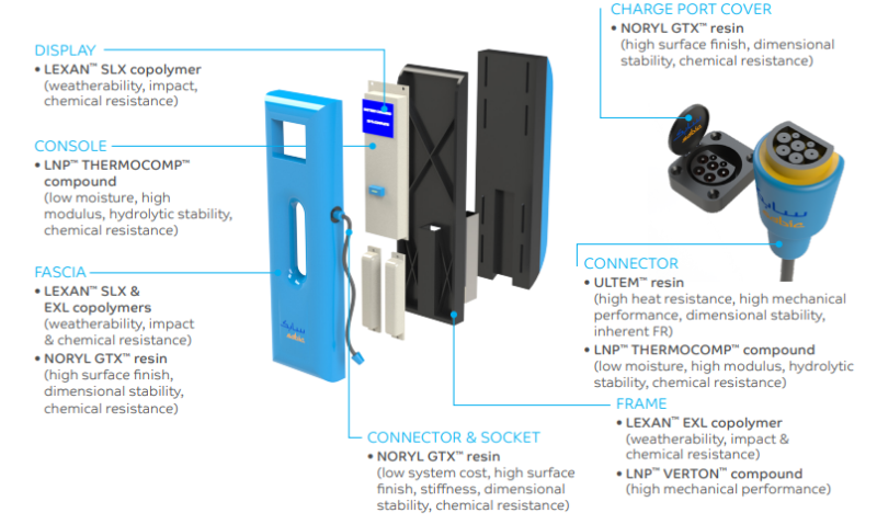
Empowering Electric Vehicle Supply Equipment
  • Superior heat resistance
  • Excellent dimensional stability
  • Hydrolytic and chemical stability
  • Inherent non-chlorinated, non-brominated FR

Electric Vehicle Supply Equipment

Innovations in Healthcare Designs

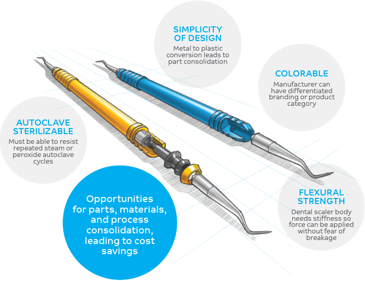
Patient and practitioner comfort has been at the forefront of thriving dental practices. Improving designs and ergonomics, reducing weight and balancing cost effectiveness are important to dental device manufacturers. ULTEM™ resin is an ideal candidate material for metal replacement and part consolidation that can help design engineers create dental devices that are simple, strong, esthetic and easy to use.

The image below is a conceptual artist's rendering of a dental hand tool, where eight internal and external parts can be consolidated to three parts, creating processing cost savings. of added benefit is the lightweight feature of ULTEM™ resin, providing dental hygienists better ergonomics with less physical strain.

ULTEM™ Resin : Conceptual Artist's Rendering Of A Dental Hand Tool

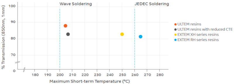
ULTEM™ Resin Thermo Optical Portfolio

ULTEM resins to address material requirements for the optoelectronics industry, including the ability to withstand the high heat of typical opto-electronic solder processes. These resins have near IR light transmission with stable signal quality and are tested according to industry aging standards like telcordia.

ULTEM™ Resin : Thermo Optical Portfolio

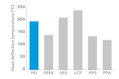
Heat Deflection Temperature

ULTEM™ Resin : Heat Deflection Temperature Graph

Thermoplastic Solutions for Automotive Oil Pumps

ULTEM™ resin, from SABIC’s Specialties business, is a lighter weight alternative to metal that offers robust mechanical strength, thermal resistance, and excellent dimensional stability. ULTEM resin also has demonstrated micron level tolerancing (>700 million cycles) in harsh applications such as cylinder deactivation valves. Additionally, when ULTEM resin is used in combination with LNP™ LUBRICOMP™ compounds, SABIC’s unique wearresistant lubrication technology, further value can be realized through higher production rates, reduction of friction, and up to a 20% decrease in Noise Vibration Harshness (NVH).


Potential Savings With an Ultem™ Resin Solution

ULTEM™ Resin : Potential Savings With an Ultem™ Resin Solution

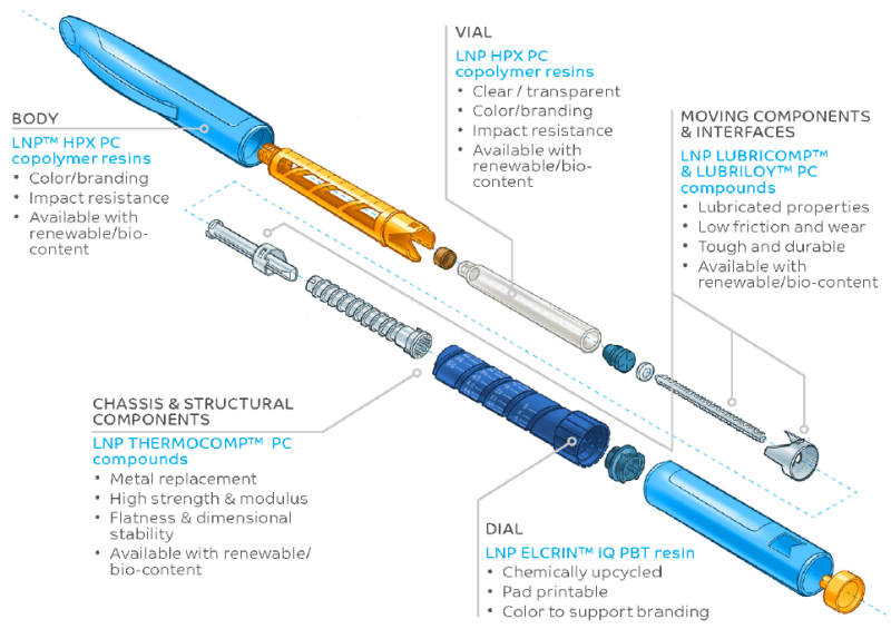
Drug Delivery Devices Application Development Process

Drug pens and autoinjectors are used for the subcutaneous delivery of biopharmaceuticals and offer patients the ability to self-administer medication. In recent years, significant developments in device design have helped to improve patient experience, compliance and sustainability. Following the trend of convergence with consumer electronics, medical device advancements include enabling enhanced usability and wireless connectivity. Additionally, streamlining design & manufacturing can help control costs and increase productivity.

SABIC’s Specialties offers a wide range of potential solutions for healthcare including structural and functional biocompatible materials, FDA food compliant color packages and sustainable options with renewable content. SABIC’s resins have value-added services, including design support, mold-flow analysis, testing and predictive engineering capabilities, which are available for each step of your application development process.

ULTEM™ Resin : Drug Pens and Autoinjectors

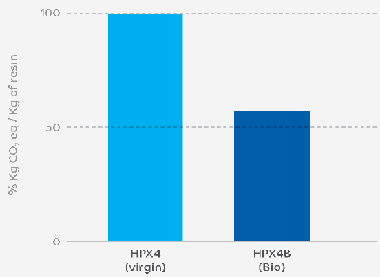
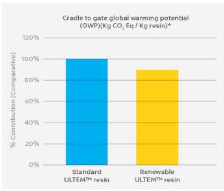
IPCC CO₂ Equivalent Analysis

Internal LCA Analysis: IPCC 2013 GWP 100A V1.03 calculated following the general principles of life cycle assessment (LCA) according to the ISO 14040 guideline, The carbon footprint estimate is for the grade when manufactured in Benoi, Singapore.

ULTEM™ Resin : IPCC CO₂ Equivalent Analysis


  • Potential drop in solution with no tooling changes
  • Better carbon/energy footprint
  • Equivalent color space
  • Requalification may not be required
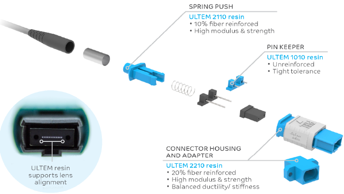
ULTEM™ Resins In Multi-fiber Push On (MPO) Connectors

A great advantage of MPO is the bundling of 8-32 connections in one plug. This improves handling, space and costs versus the use of individual fiber connections. However, the alignment of the rows of fibers is a key challenge, introducing potential insertion loss and reflection issues.

SABIC’s ULTEM™ resins are often used for multi-fiber push on (MPO) connectors in highspeed data centers and optical fiber networks. The high-performance material can address the fiber alignment issue thanks to its excellent dimensional stability under a wide range of temperatures and moisture levels. In addition, the high strength, high modulus and practical ductility of ULTEM™ resins can help enable advanced design features like thin-wall components with precise connections.
 

ULTEM™ Resins In Multi-fiber Push On (MPO) Connectors

PES to Ultem Resin Conversion - Case Study

Our customer observed improvements in the following areas:

  • ~7% lower specific gravity: decreases material needed to make parts
  • ~6% production yield increase: ULTEM resin ~94% useable yield vs. PES ~88%
  • ~6% increase in machine throughput
  • Increased confidence in supply chain


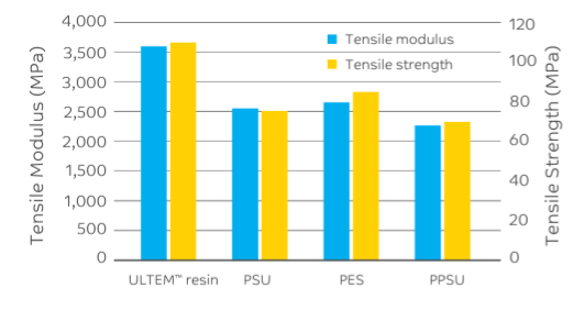
Mechanical Performance

ULTEM™ Resin : Mechanical Performance


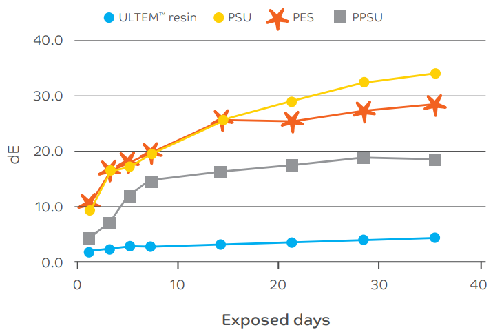
UV Resistance (ASTM G26)

ULTEM™ Resin : UV Resistance (ASTM G26)


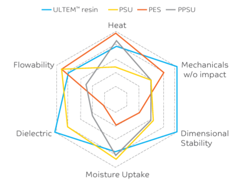
ULTEM™ Resin VS. Sulfone Polymers


ULTEM™ Resin : ULTEM™ Resin VS. Sulfone Polymers


Chemical Resistance

  ULTEM™ resin PES PSU PPSU
Aromatic Hydrocarbons 3 1 1 4
Aliphatic Hydrocarbons 10 10 7 10
Chlorinated Hydrocarbons 3 3 1 5
Alcohols 10 7 7 10
Inorganic Base 1 10 10 10
Acetates / Ketones 4 1 1 4
Acids 7 7 7 7

(1=poor; 10=excellent)


Processing Introduction

The Key Five Things to Consider

  • Follow recommended drying conditions before processing high heat resins.
  • Resins are shear sensitive
  • High temperature materials require high process temperatures.
  • Tooling & part design are important for a successful trial.
  • Processing & application testing requires attention to details!


Injection Molding

Injection molding machine must have.

  • Adequate plastic injection pressure

138 MPa Minimum (207 MPa preferred)

  • High temperature capability - 425°C (800°F)
  • Barrel Utilization

Target 30-80% (Residence time between 2 and 5 minutes ideally)

  • Precise nozzle temperature control

High watt density bands preferred

  • Adequate clamp tonnage

3-5 tons/in2 projected area

  • Screw - Low Shear Design

2.0 to 2.3:1 Compression Ratio (GP design works with 2.5:1)


Temperature Control

  • Able to uniformly heat molding surfaces to 150-200C (300-392F) depends on resin grade.


Drying, resin dryer must have

  • Dew point monitoring, -40°C dew point capable
  • High temperature package

175°C (350°F) capability for EXTEM with after cooler on return air

  • Equipped with spreader cone and resin level completely covers cone
  • Resin transport hoses must be:

High temperature & free of contaminants

Ideally short in length.


Mold Considerations

  • Generous gating – Bigger is better!
  • Complete a mold filling analysis if possible
  • Adequate mold venting
  • Cooling circuits on cavity/ core inserts and retainer plates
  • Insulation board on top clamp plate (at a minimum) Top & Bottom preferred


Troubleshooting

Discoloration

  • The appearance of a non-uniform color distribution in the molding
  • Purge heating cylinder
  • Lower melt temperature by:
  1. Decrease cylinder temperature
  2. Decrease screw speed
  3. Decrease back pressure
  • Lower nozzle temperature
  • Shorten overall cycle
  • Increase back pressure to improve melt homogeneity
  • Check hopper and feed zones for contaminants
  • Check for proper cooling of ram and feed zone
  • Provide additional vents in mold
  • Move mold to a smaller shot size press to reduce barrel residence time.
  • Check screw design, a high compression ratio screw may cause excessive shear heating.


Black Specks

Small black areas (spots) inside the material, mostly present in transparent ULTEM™ / EXTEM™ grades.

  • Purge with ULTEM/EXTEM regrind or un-dried ULTEM/EXTEM resin
  • Purge periodically after shut-off until cylinder temperature falls below 660°F (350°C); then continue with purging until shutdown is complete.
  • Bank set temperatures of machine at 350°F (180°C) when not molding (EXTEM @ 400°F (204°C)
  • Decrease nozzle temperature
  • Check temperature at feed section, low temperatures may cause mechanical degradation.
  • Check heater bands and control
  • Check nozzle tip, check ring assembly, nozzle adapter, and end-cap for hang-up areas


Burn Marks

They are usually caused by overheating of the material due to entrapped air (diesel effect): this causes the darkening in color

  • Decrease injection speed
  • Decrease booster time
  • Decrease injection pressure
  • Check venting channels for dirt
  • Use programmed injection
  • Improve venting of tool  Alter position of gate and/or increase gate size


Brittleness / Cracking

The molded product is failing prematurely either after molding, during testing, or during normal usage.

  • Dry resin properly (<0.02% moisture content)
  • Improve weld line strength (see weld lines)
  • Decrease molded in stresses (see stresses)
  • Lower melt temperature by: 
    • Decrease cylinder temperatures
    • Decrease screw speed
    • Decrease back pressure
  • Check for voids in the part
  • Check for contamination
  • Decrease the amount of regrind in feed
  • Check part design (sharp corners, wall thickness transitions, bosses etc,..)
  • Check tooling (venting, ejection system)
  • Investigate for chemical attack.


Gloss

  • Increase mold temperature
  • Increase melt temperature
  • Increase injection speed
  • Increase injection pressure
  • Check surface of the mold for polish
  • Clean vents
  • Increase venting


Weld Lines / Knit Lines

These lines occur where two melt flow fronts in the mold meet. The streams of plastic should be hot enough to fuse adequately. Weld lines are not just surface marks, but can be points of weakness: notches, stress raisers.

  • Increase injection speed
  • Increase injection pressure
  • Increase injection hold time
  • Raise the mold temperature
  • Raise melt temperature by increasing cylinder temperatures
  • Vent the cavity in the weld area
  • Provide an overflow well next to the weld area
  • Change gate location to alter flow pattern


Jetting / Worming

A serpentine line on the part surface emanating from the gate

  • Decrease injection speed
  • Increase melt temperature by:
    • Increase cylinder temperature
    • Increase screw speed (unfilled)
    • Increase back pressure (unfilled)
  • Increase mold temperature
  • Increase gate size
  • Decrease gate land length
  • Modify gate location or angle: directly into wall or pin
  • Avoid gating at thick section.


Voids

Vacuole hollows in the molding, due to thermal shrinkage that draws material away from the fluid core of a part.

  • Decrease injection speed
  • Increase holding time
  • Reduce melt temperature
  • Increase mold temperature
  • Check gate size and reduce gate land length
  • Increase gate size and reduce gate land length
  • Increase nozzle size and/or runner system
  • Redesign part to obtain equal wall sections.


Molded in Stress

These molded in stresses can result in part brittleness. Usually caused by highly oriented polymer flow.

  • Decrease injection speed
  • Increase melt temperature
  • Increase mold temperature
  • Decrease injection pressure
  • Increase gate size
  • Increase nozzle orifice diameter


Sink Marks

Visible defects resulting from insufficient cooling before removal from the mold. A heavy rib intersecting a thin wall may show up as sink marks: these are very difficult to eliminate by varying processing conditions.

  • Increase injection hold time
  • Increase injection pressure
  • Reduce melt temperature
  • Reduce mold temperature
  • Decrease injection speed
  • Enlarge and/or add vents to mold parting line
  • Increase size of sprue and /or runners
  • Increase gate size and reduce gate land length
  • Relocate gate next to heavy or thicker areas
  • Core out heavy wall sections where possible


Sticking In Sprue Bushing

At end of cycle, the sprue does not release from the mold but sticks in the sprue bushing.

  • Decrease injection pressure
  • Increase injection hold time
  • Decrease booster time
  • Increase mold close time
  • Decrease mold temperature at sprue bushing
  • Leave nozzle against mold: no pull back
  • Raise nozzle temperature
  • Check for correct seat between nozzle and sprue
  • Check sizes and alignment of holes in nozzle and sprue bushing
  • Nozzle orifice should be .030” smaller in diameter than sprue bushing “O” diameter 
  • Check polishing of sprue
  • Provide more effective sprue puller
  • Make sure sprue has enough draft angle for easy release
  • If the sprue is stringing, increase or add screw decompression


Sticking In Cavity / Core

At the end of cycle, the part does not release from the mold but sticks on the core or cavity.

  • Decrease injection pressure
  • Decrease hold time
  • Decrease booster time
  • Adjust feed for constant cushion
  • Increase mold closed time
  • Adjust the cavity/core temperatures to a 20° differential between mold halves
  • Decrease cylinder and nozzle temperature
  • Check mold for undercuts and /or sufficient draft.


Streaks

  • Decrease melt temperature
  • Decrease nozzle temperature
  • Decrease back pressure
  • Decrease injection speed
  • Decrease screw speed
  • Decrease cushion size
  • Check for contamination
  • Increase the cavity venting
  • Increase gate size
  • Increase nozzle orifice diameter
  • Check for material hang-up


Warpage, Part Distortion

  • A dimensional distortion in the molded part, usually bowing or bending of the part.
  • Equalize temperature of both mold halves
  • Observe mold for uniform part ejection
  • Check handling of parts after ejection from mold
  • Increase injection hold time until gate freezes
  • Increase mold closed time
  • Increase or reduce injection pressure
  • Increase or reduce mold temperature
  • Set differential mold temperatures to counteract warpage due to part geometry
  • Use shrink fixtures and jigs for uniform cooling of the part
  • Check gate locations and total number of gates to reduce orientation
  • Increase gate dimensions
  • Redesign part to equalize wall variation in molded part-thick and thin walls in the same part create differential shrinkage stresses
  • Check cooling line layout, unbalanced cooling promotes warpage.


Splay Marks, Silver Streaks

The result of:

  1. Moisture on the pellets which should be removed under recommended drying times & temperatures
  2. Products of degradation due to overheating.
  3. Residual non-aqueous volatiles in material.
  • Dry resin properly excess moisture may cause splay
    • Lower melt temperature by:
    • Decrease cylinder temperatures
    • Decrease screw speed
  • Decrease back pressure
  • Lower nozzle temperature
  • Decrease injection speed
  • Shorten or eliminate screw decompression
  • Shorten overall cycle
  • Increase or decrease mold temperature
  • Check for contamination (e.g.water or oil leaking into mold cavity)
  • Move mold to a smaller shot size press
  • Check for drooling
  • Open gates
  • Check hot runner system
  • Increase nozzle orifice
  • Increase sprue and runner size


Solutions for Advanced Driver Assistance Systems (ADAS)

The importance of passenger, occupant and pedestrian safety is driving automakers and their suppliers to upgrade their ADAS offerings to further advance the performance and reliability of assisted driving. As adoption rates rise, the number of safety features and onboard electronic systems per vehicle increases each year, requiring engineers to seek out material solutions for light weighting and increased design flexibility.

Radar systems are an integral part of the ADAS system supporting features such as Adaptive Cruise Control (ACC), Automatic Emergency Braking (AEB) and Forward Collison Warning (FCW). Radar sensors constantly sense the distance between
vehicles in real-time to improve driving efficiency and safety. Therefore, these units require material solutions offering effective Electromagnetic Interference (EMI) shielding and radar absorption properties to ensure that cross-interference does not disrupt the various system components that protect drivers, passengers an,d pedestrians.

SABIC’s highly specialized thermoplastics can help engineers improve radar sensor technologies using materials that aid in light weighting, metal replacement and improved design flexibility. Providing automakers and their suppliers with high performance solutions to help them address the ever-changing ADAS landscape, as well as to identify potential system cost reductions.

Our portfolio offers:

  • EMI shielding to eliminate cross talk
  • Radar absorption to reduce cavity resonance
  • Thermal conductivity for heat management
  • Superior mechanical properties and resistance to commonly used automotive chemicals

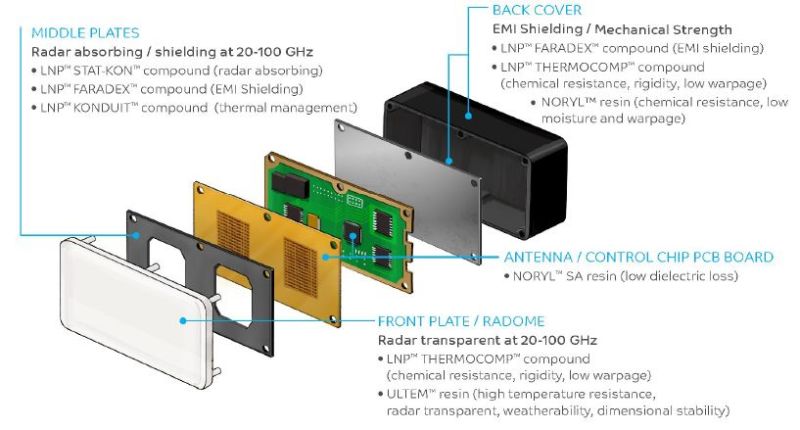
SABIC Solutions for Radar Sensor System Applications

Ultem™ Resin : Solutions for Radar Sensor System Applications


Battery Pack Peripherals

Lightweight Battery Pack Peripherals

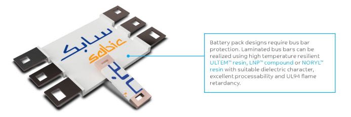
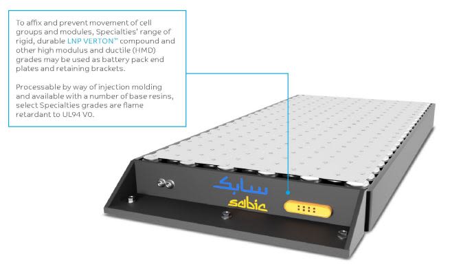
Depending on material and design requirements, SABIC’s Specialties business can provide a number of materials for electric vehicle battery packs, including bus bar holders, covers, brackets, end plate assemblies and enclosures for battery management systems, control units, fuses and relays, etc.

Ultem™ Resin : Battery Pack Peripherals

Ultem™ Resin : Battery Pack Peripherals 2

ISCC+ Certified Renewable Bio-based ULTEM™ Resins

A new portfolio of bio-based ULTEM™ resins that deliver a lower carbon footprint while offering exactly the same high performance and processability as incumbent ULTEM materials.

These breakthrough polyetherimide (PEI) materials are the first certified renewable high temperature, amorphous resins available in the industry for potential use in challenging applications in consumer electronics, aerospace, automotive and other industries.

SABIC Sustainability 

CIRCULAR ECONOMY inspires SABIC to adapt our processes to the use of renewable and recycled feedstock, and to create durable, recyclable product design solutions for our customers.

Bio-Based Feedstock 

  • Replacing fossil-based feedstock
  • Animal and palm oil free
  • Derived from waste or residue, such as crude tall oil
  • Second generation renewable feedstock
  • ISCC+ certified value chains


SABIC ISCC+ Certified Renewable ULTEM™ Resin Solutions

ULTEM™ Resin : SABIC ISCC+ Certified Renewable Resin Solution

For every 100 kg of this ULTEM™ resin, 25.5 kg of oil-oased materials have been replaced by bio-based materials, based on mass balance approach.


Life Cycle Assessment (LCA) 

Life Cycle Assessment (LCA)

Potential Market and Applications

Consumer Electronics

  • Wearables
  • Mobile devices


Automotive

  • Connectors
  • Sensors
  • Valves


Healthcare

  • Surgical devices
  • Sterilization trays


Aerospace Interiors

  • Personal service units
  • Panels and trim


Electrical/Electronics

  • 5G networking infrastructure
  • Connectors


Case Study

EziSurg Medical Relies on SABIC’s ULTEM™ Resin for High-performance Premium Ultrasonic Scalpel Shears

EziSurg Medical Co., Ltd. (ESM) specializes in the development and commercialization of high-end, minimally invasive surgical instruments. The Shanghai-based company, a China market leader in medical scalpel systems, was looking for a material solution to help maintain and build on their competitive strength in these demanding medical devices, both locally and abroad. Their goal was to find a polymer capable of outperforming incumbent materials, including polysulfones, in the next generation of their fast-cutting easyUS® premium ultrasonic scalpel shears.

Read Case Study

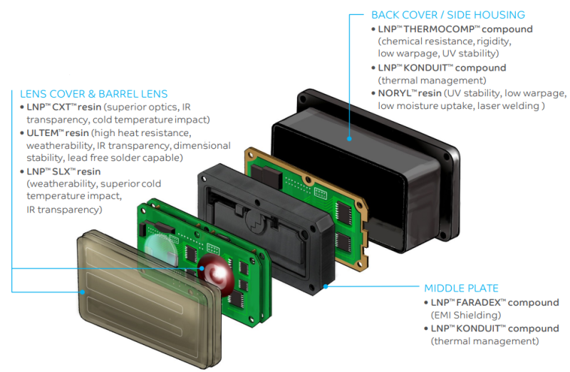
Lidar Material Solutions for Advanced Driver Assistance Systems

ULTEM™ Resin : Lidar Material Solutions for Advanced Driver Assistance Systems