Knowde Enhanced TDS
Identification & Functionality
- Chemical Family
- Fillers Included
- Polymer Name
- Plastics & Elastomers Functions
- Technologies
Features & Benefits
- Materials Features
Applications & Uses
- Applications
- Plastics & Elastomers End Uses
- Plastics & Elastomers Processing Methods
- Application in Automotive Part with EMI Shielding Properties
- Original housing: Metal (high shielding level, expensive in production, heavy, design limitations)
- iPolyCond solution: Polypropylene with polyaniline and carbon nanotubes, with the required EMI shielding protection
- Improvements: Design flexibility, weight reduction, 25% cheaper, recyclable
- Application in Blood Pressure Monitoring Device
- Original housing: Stainless steel fiber filled PC/ABS (difficult to manufacture, final product failed due to poor physical properties)
- iPolyCond solution: PC/ABS filled with carbon nanotubes, with at least 30 dB shielding
- Improvements: Toughness, recyclable, ease of manufacture, better surface quality
- Application in Military Radio with High Level EMI Shielding
- Original housing: Metal (high shielding level, expensive in production, heavy, design limitations)
- iPolyCond solution: PC/ PBT with carbon nanotubes and stainless steel fibers, with 60 dB shielding
- Improvements: Toughness, easily molded, 60% weight reduction, 40% cheaper
- Application in Grounding Plug Earth Pin
- Original: Brass grounding pin (expensive, specialist product)
- iPolyCond solution: Polycarbonate with carbon nanotubes
- Improvements: Ease of manufacture, 80% weight reduction, plug is 40% cheaper, recyclable
Properties
- Flame Rating
- Physical Properties
| Value | Units | Test Method / Conditions | |
| EMI Shielding (at 100MHz/1GHz) | 34 | dB | Reflectometer |
| Flexural Modulus (at 2mm/min) | 12.9 | Gpa | ISO 178:2003 |
| Heat Deflection Temperature (at 1.8 MPa) | 255 | °C | BS EN ISO 75-1&2 |
| Izod Impact Strength (at 23 ± 2°C) | 4.4 | KJ/m² | ISO179-1:2001 |
| Specific Gravity | 1.64 | g/cm³ | BS EN ISO 1183-1:2004 |
| Tensile Modulus (at 1mm/min) | 10.8 | Gpa | ISO 527-2:1997 |
| Tensile Strain (at Break, 50mm/min) | 1.4 | % | ISO 527-2:1997 |
| Tensile Strength (at Break, 50mm/min) | 151 | MPa | ISO 527-2:1997 |
| Volume Resistance (at 23 ± 2°C) | 4x10³ | Ohm.cm | BS 2044:1984 /3 |
Regulatory & Compliance
- Certifications & Compliance
Technical Details & Test Data
- Electromagnetic Interference vs Conductive Polymer Composites
The Challenge : Electromagnetic Interference
Unwanted electromagnetic interference effects occur when sensitive devices receive electromagnetic radiation that is being emitted - whether intended or not - by other electric or electronic devices such as microwaves, wireless computers, radios and mobile phones. As a result, the affected receiving devices may malfunction or fail.The effects of electromagnetic interference are becoming more and more pronounced, caused by the demand for high-speed electronic devices operating at higher frequencies, the more intensive use of electronics in e.g. computers, communication equipment and cars, and the miniaturization of these electronics. For example, mobile phones and smartphones are typically operating at 800-4900 MHz, and around 2 GHz for data transmission through Universal Mobile Telecommunications Systems (UMTS). Compact, densely packed electronic components produce more electronic noise.
These trends indicate the need to protect components against electromagnetic interference (EMI) in order to decrease the chances of these components adversely affecting each other or the outer world. The effects of electromagnetic interference can be reduced or diminished by positioning a shielding material between the source of the electromagnetic field and the sensitive component. This protection may be achieved by making the housing of electronic components electronically conducting.
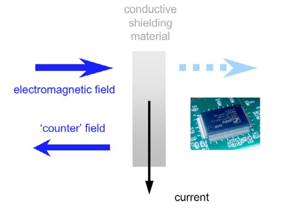
Electrical conductivity is a prerequisite for an EMI shielding material. This is due to the physical phenomenon that electric fields and varying magnetic fields induce currents in the electrically conducting shielding material. In turn, these currents generate counteracting fields which weaken - or in the ideal case cancel - the originally applied fields. Ideally, external fields stay outside the shielding material, and internal fields stay inside.
As EMI shielding is composed of reflection and absorption contributions, both the conductivity in the volume of the protecting material as well as the thickness of the material may be of importance. In a practical way, the extent of shielding is also subject to the size and shape of openings in the shield. For example, at a frequency of 5 GHz the opening must be less than 52 mm for effective EMI shielding.
Very much related to EMI shielding is the protection against electrostatic discharge (ESD) in electronic devices. ESD is the uncontrolled transfer of static charge between two objects with different electrical potential. For ESD protection surface conductivity is important, to allow a fast and controlled discharge of static charge.
The Solution : Conductive Polymer Composites
Housings for electronic products (e.g., computers, communication devices) and business equipment (including devices for payment processing) are often made of engineering plastics. A particular problem for shielding is that plastics generally have excellent electrical insulation properties (as can be seen from their usefulness as insulation for electric wires). With a typical electrical conductivity of <10–14 ohm-1.cm-1, these engineering plastics cannot shield electronic devices from electromagnetic radiation. For EMI shielding the conductivity should be >10–2 ohm-1.cm-1, resulting in a (volume) resistivity of <102 ohm.cm.Filling a matrix of engineering plastic with small volume fractions of an electrically conductive material combines the availability of a housing made of shielding material with the advantages of traditional polymer processing techniques. These advantages include the use of existing compounding equipment - so no large new investments have to be made - and the ease of manufacturing small, complex shapes in a one-step process.
Several fillers can be used. Traditionally, metal or carbon-black particles have been used as electrically conductive filler materials. A high level of these fillers can be detrimental for the processability, density and surface quality of the material, the costs and mechanical properties of the molded product, and may cause wear to the processing equipment. Therefore, an interesting solution is to use novel filler materials such as conductive carbon nanotubes (CNT) with a filler content that is as low as possible. In this way, conductivity and sufficient mechanical stability will be provided to the material while the original plastic processing properties will remain the same.
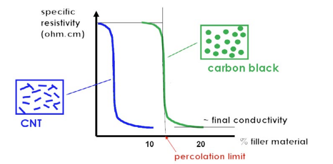
When the concentration of electrically conductive particles in a composite exceeds a certain level (the ‘percolation limit’), the particles come into contact with each other and form a continuous path in the material for electrons to travel. In this way, the composite material has become electrically conductive. The conductivity of the filler material will be the upper limit for the electrical conductivity of the entire composite.
The percolation limit is dependent upon the shape of the conductive particles. For traditional spherical-shaped fillers at a random distribution, ~10–20% has to be added before the composite will be electrically conductive. The higher the aspect ratio (length-towidth ratio) of the particles, the lower is the concentration for percolation needed to take place. CNT with a diameter of a few nanometres and a length of micrometers (i.e. a high aspect ratio) can form a conductive network at much lower volume fractions - and potentially lower costs - than cheaper, traditional fillers such as carbon fiber and carbon black.
- Comparison With Alternative Solutions
Suitable matrix polymers Benefits/properties of these
polymers with CNTPolypropylene (PP) Good toughness possible Polyamide 12 (PA 12) Wire coating, high chemical resistance Polyamide 6/66 (PA 6/66) Tough, easy to mold, high temperature
resistancePolycarbonate (PC) Much better properties than obtainable
with carbon blackPolycarbonate/Acrylonitrile-
Butadiene-Styrene (PC/ABS)Very good toughness and good
mouldabilityPolycarbonate/Polybutylene
terephthalate (PC/PBT)Very good toughness for housings
with UV resistanceGlass filled Polyphenylene
sulfide (PPS)Very high stiffness and very high
temperature resistanceThermoset Polyurethane (PU) (Very) large moldings The incorporation of small volume fractions of novel, non-metallic electrically conducting fillers in a non-conducting plastic matrix by means of compounding as a one-step process forms the basis of conductive polymer composites. The filler materials used here are conductive carbon nanotubes (CNT). CNT, especially those of a multi-wall composition, multi-wall carbon nanotubes (MWCNT), which can best be described as multiple layers of graphite rolled in on themselves, are known to conduct electricity.
Comparison with alternative solutions
Due to their high electrical conductivity (~106 ohm-1.cm-1), metals are particularly suitable as shielding material against electromagnetic fields. This can be a self-supporting full metal shielding, but also a sprayed, painted or electrolessly applied conductive coating (e.g., nickel) on a supporting material such as plastic. Another option is the incorporation of stainless steel powder or fibers as conductive filler in a plastic matrix.However, there are a few drawbacks to using metal as a shielding material. The weight of the ‘heavy’ metal can be an issue in the case of full metal shielding and plastic matrices with high metal filler content, especially in applications in which mass should be as low as possible. Furthermore, metals are prone to corrosion. To produce metal coatings, at least two processing techniques must be applied - one for the support and one for the coating - which can be costly. It will also be difficult to apply these coatings onto complicated-shaped objects. In addition, the long-term adhesion of the coating to the support has to be reliable.
- Design & Processing
The most common technique for shaping complex plastic products (e.g. housings for electronic applications) is injection molding. Many parameters can be varied in the injection molding process, and many of these parameters can have a significant positive (+), negative (-) or neutral (0) influence on the shielding performance of the product:
Parameter Volume
resistivitySurface
resistivityReflection Mold temperature increases ➖ ➕ 0️ Mold temperature above Tg ➖ ➕ ➖ Injection speed increases ➖➖➖ ➕➕ ➖ Wall thickness increases ➕➕ Distance from the gate increases ➕ Surface texture 0️ Flow direction ➖ To minimize shear during filling of the part mold, it is advisable to avoid sharp corners in plastics parts, and to try to ease the flow by replacing the sharp corners by rounded ones. As part of the effect of shear stress in the part, on the design stage we have to minimize the sharp corners, giving them generous radii to expedite flow of the conductive melt.
Combining the use of low velocities with a wider injection gate facilitates the flow of the conductive plastic into the cavity. In this way, it is possible to ensure complete filling of the cavity without the need for increasing the injection speed. Higher speed profiles increase the possibility of shear stresses in the injected part.
It is possible to cover all the range of usual part thicknesses that have been used in the thermoplastic molding industry. The use of parts with higher or lower thickness will be determined by the final properties or special requirements to reach in its use. The best reflection values were obtained on parts that were less thick.
For CNT and steel-fiber filled compounds, it is necessary to avoid extremely long flow lengths because the longer the flow, the more shear is imparted to the compound, causing a loss of fiber integrity.
Based on our experience, the molds should be designed to minimize melt turbulence, necessitating gates and runners that are larger than those for unfilled resins and similar to those used for other fiber filled materials.
Guidelines for gating of conductive filled materials include a minimum gate depth of 1.5 mm, with a preference for a gate depth of 2.3 mm to 2.5 mm. As a result, pinpoint, tunnel, and subgates are not recommended, and tab or sprue gates are preferred. Multiple gating may be necessary to achieve the best dispersion.
Full circular runners are recommended for optimum flow because this minimizes the number of bends or turns to prevent masterbatch breakage. Cold slug wells are recommended at the end of 90o angles.
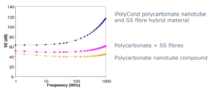
- Typical iPolyCond Materials Frequency Comparison