Knowde Enhanced TDS
Identification & Functionality
- Chemical Family
- Fillers Included
- Polymer Name
- Plastics & Elastomers Functions
- Technologies
Features & Benefits
Applications & Uses
- Markets
- Plastics & Elastomers End Uses
- Plastics & Elastomers Processing Methods
Properties
- Flame Rating
- Mechanical Properties
- Thermal Properties
- Electrical Properties
- Other Properties
- Rheological Properties
| Value | Units | Test Method / Conditions | |
| Tensile Modulus | 13300.0 | MPa | ISO 527-1/-2 |
| Tensile Modulus (120°C) | 6100.0 | MPa | ISO 527-1/-2 |
| Tensile Modulus (160°C) | 4100.0 | MPa | ISO 527-1/-2 |
| Tensile Modulus (200°C) | 3600.0 | MPa | ISO 527-1/-2 |
| Stress at Break | 180.0 | MPa | ISO 527-1/1-2 |
| Stress at Break (120°C) | 75.0 | MPa | ISO 527-1/-2 |
| Stress at Break (160°C) | 55.0 | MPa | ISO 527-1/-2 |
| Stress at Break (200°'C) | 45.0 | MPa | ISO 527-1/-2 |
| Strain at Break | 2.4 | MPa | ISO 527-1/-2 |
| Strain at Break (120°C) | 5.0 | % | ISO 527-1/-22 |
| Strain at Break (160°C) | 5.5 | % | ISO 527-1/-2 |
| Strain at Break (200°C) | 5.8 | % | ISO 527-1/-2 |
| Flexural Modulus | 12000.0 | % | ISO 178 |
| Flexural Strength | 250.0 | MPa | ISO 178 |
| Flexural Modulus (120°) | 4300.0 | MPa | ISO 178 |
| Flexural Modulus (200°c) | 3400.0 | MPa | ISO 178 |
| Charpy Impact Strength (+23°C) | 60.0 | kJ/m² | ISO 179/1eU |
| Charpy Impact Strength (30°C) | 65.0 | kJ/m² | ISO 179/1eU |
| Charpy Notched Impact Strength (+23°) | 13.0 | kJ/m² | ISO 179/1eA |
| Charpy Notched Impact Strength (-30°C) | 12.0 | kJ/m² | ISO 179/1eA |
| Izod Impact Strength (+23°C) | 60.0 | kJ/m² | ISO 180/1U |
| Izod Notched Impact Strength (+23°C) | 16.0 | kJ/m² | ISO 180/1A |
| Izod Notched Impact Strength (-40°C) | 13.0 | kJ/m² | ISO 180/1A |
| Rockwell Hardness (R scale) | 117.0 | — | ISO 2039-2 |
| Value | Units | Test Method / Conditions | |
| Melting Temperature (10°C/min) | 280.0 | °C | ISO 11357-1/-3 |
| Temperature of Deflection under Load (1.80 MPa) | 258.0 | °C | ISO 75-1/-2 |
| Coefficient of Linear Thermal Expansion (Parallel) | 0.15 | E-4/°C | ISO 11359-1/-2 |
| Coefficient of Linear Thermal Expansion (Normal) | 0.48 | E-4/°C | ISO 11359-1/-2 |
| Coefficient of Linear Thermal Expansion (Parallel, above Tg) | 0.11 | E-4/°C | ISO 11359-1/-2 |
| Coefficient of Linear Thermal Expansion (Normal, above Tg) | 1.1 | E-4/°C | ISO 11359-1/-2 |
| Value | Units | Test Method / Conditions | |
| Volume Resistivity | min. 1E13 | Ohm m | IEC 62631-3-1 |
| Electric Strength | 33.0 | kV/mm | IEC 60243-1 |
| Comparative Tracking Index | 175.0 | V | IEC 60112 |
| Dissipation Factor (5GHz) | 55.0 | E-4 | IEC 61189-2-721 |
| Relative Permittivity (5GHz) | 3.8 | — | IEC 61189-2-721 |
| Value | Units | Test Method / Conditions | |
| Density | 1600.0 | kg/m³ | ISO 1183 |
| Value | Units | Test Method / Conditions | |
| Molding Shrinkage (Parallel) | 0.2 | % | ISO 294-4 |
| Molding Shrinkage (Normal) | 0.5 | % | ISO 294-4 |
Regulatory & Compliance
- Certifications & Compliance
Technical Details & Test Data
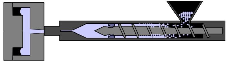
- Machinery for Injection Molding
Xytron™ grades can be processed on general injection molding machines.
Screw Geometry
- Typically 3-zone screw designs with volumetric compression ratios of approximately 2.5 work fine.
Steel Type
- Abrasive-resistant steel types which are generally used for glass fiber reinforced, high temperature, polyamide or PPS materials are also to be used for the Xytron™ grades in tools, nozzles and screws. Failing to do so may result in wear, especially of the screw/barrel (due to the high temperatures involved there), which can lead to decreasing processing performance.
Nozzle Temperature Control
- The use of an open nozzle with good temperature control and an independently-controlled thermocouple nearby the tip and heater bands with sufficient output is recommended.
Hot Runner Layout
- Try to achieve a close contact with your hot runner supplier and Envalior as the material supplier, to be sure that the right hot runner system is chosen.
- When processing Xytron™ with hot runners, keep in mind these basic rules:
- Central bushing heated separately
- Only use external heated system
- Manifold heated from both sides
- Tip with thermocouple in front (near gate)
- Very accurate temperature control in the gate area
- Temperature Settings For Injection Molding
Mold Temperature
- Xytron™ can be used with a wide range of tool temperatures (140 - 150°C / 284 - 302°F). However, we recommend a low mold temperature for parts with thick walls and a high mold temperature for good dimensional stability, flow properties and surface esthetics.
Barrel Temperature
- Optimal settings are governed by barrel size and residence time. Furthermore, the level of glass and/or mineral reinforcement has to be taken into account.
Mold/Tool Measured melt Nozzle Front Center Rear 140 - 150°C
284 - 302°F310-340°C
590-644°F310-340°C
590-644°F320-340°C
608-644°F310-330°C
590-626°F300-320°C
572-608°F
Melt Temperature
- To generate a good and homogeneous melt, the melt temperature should always be above 310°C / 590°F. Optimal mechanical properties will be achieved at melt temperatures between 310-340°C / 590-644°F.
- We advise to frequently measure the melt temperature by pouring the melt in a Teflon cup and inserting a thermo probe into the melt.
Hot Runner Temperature
- A hot runner temperature set to the same level as the nozzle temperature should work fine and not lead to excessive overheat of the Xytron™ grade. When starting up, an increased tip temperature may be necessary to overcome a frozen nozzle.
- General Processing Settings For Injection Molding
Screw Rotation Speed
- To realize a good and homogeneous melt, it is advised to set a screw rotation speed resulting in a plasticizing time that is just within the cooling time.
- The rotational speed of the screw should not exceed 6500 / D RPM (where D is the screw diameter in mm).
Back Pressure
- Back pressure should be between 30-100 bars effective. Keep it low in order to prevent nozzle-drooling, excessive shear heating and long plasticizing times.
Decompression
- In order to prevent nozzle drool after plasticizing and retracting the nozzle from the mold, a short decompression stroke can be used. However, to prevent oxidation of the melt, which may result in surface defects on the parts, it is recommended to keep this as short as possible.
Injection Speed
- Moderate to high injection speeds are required in order to prevent premature crystallization in the mold during injection phase and to obtain a better surface finish. The recommended injection speed profile goes from fast (for sprue and runner filling) to medium (for part filling) to avoid excessive shear heating and allow air to escape from the mold.Adequate mold venting is required to avoid burning at the end of the flow path (due to diesel effect).
Injection Pressure
- The real injection pressure is the result of the flowability of the material (crystallization rate, flow length, wall thickness, filling speed). The set injection pressure should be high enough to maintain the set injection speed (use set injection pressure higher than the peak pressure if possible). Tooling air vents must be effective to allow optimum filling pressure and prevent burn marks.
Holding Time
- Effective holding time is determined by part thickness and gate size. Holding time should be maintained until a constant product weight is achieved.
Holding Pressure
- The most adequate holding pressure is the level whereby no sinkmarks or flash are visible. A too high holding pressure can lead to stresses in the part.
Cooling Time
- Actual cooling time will depend on part geometry and dimensional quality requirements as well as the tool design (gate size).
- Melt Residence Time For Injection Molding
The optimal Melt Residence Time (MRT) for Xytron™ U3020E is ≤ 6 minutes with preferably at least 50% of the maximal shot volume used. The MRT should not exceed 8 minutes.
A formula to estimate the MRT is described below:
MRT = (∏D³ρ/m) * (t/60)
Whereas:
MRT = Melt Residence Time [minutes]
D = Screw Diameter [cm]
p = Melt Density [g/cm3)
m = Shot Weight [g]
t = Cycle Time [s]Please note: In the calculation above, the hotrunner volume has not been taken into account. When a hotrunner is part of the setup, please add the hotrunner volume to the calculation.
- Startup/Shut Down/Cleaning For Injection Molding
- Production has to be started and stopped with a clean machine. Cleaning can be done with PA6-GF or PA66-GF, applicable cleaning agents or HDPE. Hot runners can also be cleaned and put out of production cleaning them with PAG-GF or PA66-GF.
- Production Breaks For Injection Molding
- During production breaks longer than a few minutes, we advise emptying the barrel. The temperature of the barrel and the hot runner [if applicable] should be reduced to a level far enough below the melting point of the compound in order to stop decomposition of the compound.
- When the hot runner, nozzle, or even the screw is blocked, be aware that under these conditions a sudden outburst of molten material can take place. Always wear personal safety protections for hand/eye/body.
Packaging & Availability
- Packaging Type
Storage & Handling
- Material Handling For Injection Molding
Storage
- In order to prevent contamination, supplied packaging should be kept closed and undamaged. For the same reason, partial bags should be re-closed before re-storage.
- Allow the material that has been stored elsewhere to adapt to the temperature in the processing room while keeping the bag closed.
Packaging
- Xytron™ grades are supplied in polyethylene bags.
Moisture Content as Delivered
- Xytron™ PPS grades show hardly any moisture pick up. The moisture content is not specified.
Conditioning Before Molding
- To prevent moisture condensing on granules, bring cold granules up to ambient temperature in the molding shop while keeping the packaging closed.
Moisture Content Before Molding
- Since Xytron™ has a low moisture pick up and is not hygroscopic, still the advise is to dry Xytron™ G4080HRE for a short time. The advisable moisture level before molding is maximum 500 ppm.
Drying
- Hot air ovens or hopper driers can be used for pre-drying Xytron™ grades, however preferred driers are dehumidified driers with dew points maintained between -30 and -40°C / -22 and -40°F. Vacuum driers with N, purge can also be used.
Moisture content Time Temperature [%] [h] [°C] [°F] as delivered 2-6 130-140 266-284 Regrind
- Regrind can be used taking into account that this regrind must be clean/low dust content/not thermally degraded/dry, of same composition and similar particle size as the original material. The acceptable level of regrind depends on the application requirements (e.g. UL Yellow Card). Be aware that regrind can cause some small color deviations.