Knowde Enhanced TDS
Identification & Functionality
- Chemical Family
- Polymer Name
- Technologies
- Product Families
Features & Benefits
- Labeling Claims
- Materials Features
- Product Features
- Significantly lower cost per wafer
- Outperforms PPS up to 20x in most processes
- High strength and stiffness promotes fewer edge defects and better uniformity
- Next generation CMP Ring material for Semicon Industry
- Extremely long wear life in CMP slurry
Applications & Uses
- Markets
- Plastics & Elastomers End Uses
Properties
- Color
- Flame Rating
- Mechanical Properties
- Thermal Properties
- Electrical Properties
- Miscellaneous Properties
| Value | Units | Test Method / Conditions | |
| Tensile Strength | 20000 | psi | ASTM D638 (8) |
| Tensile Strain (Elongation) at Break | 8.8 | % | ASTM D638 (8) |
| Tensile Strain (Elongation) at Break | 10 | % | ASTM D638 (8) |
| Tensile Modulus of Elasticity | 575 | ksi | ASTM D638 (8) |
| Shear Strength | 16000 | psi | ASTM D732 |
| Compressive Strength | 24000 | psi | ASTM D695 (11) |
| Flexural Strength | 24000 | psi | ASTM D790 (13) |
| Flexural Modulus of Elasticity | 600 | ksi | ASTM D790 |
| Hardness (14) | 120 | Rockwell M | ASTM D785 |
| Value | Units | Test Method / Conditions | |
| Glass Transition Temperature (DMA, Tan Delta) | 527 | °F | DMA |
| Thermal Conductivity (73°F) | 1.8 | BTU in./(hr. ft² ˚F) | — |
| Coefficient of Linear Thermal Expansion (-40 to 300°F) | 17 | µin./in./°F | ASTM E-831 (TMA) |
| Heat Deflection Temperature (Method A: 1.8 MPa (264 PSI)) | 532 | °F | ASTM D648 |
| Continuous Allowable Service Temperature in Air (20.000 hrs) (3) | 500 | °F | — |
| Flammability (3 mm) (5) | V-0 | — | UL 94 |
| Value | Units | Test Method / Conditions | |
| Electric Strength | 580 | Volts/mil | ASTM D149 |
| Surface Resistivity | 10000000000000 | Ohm/sq. | ANSI/ESD STM 11.11 |
| Dielectric Constant (1 MHz) | 4.2 | — | — |
| Dissipation Factor (1 MHz) | 0.026 | — | — |
| Value | Units | Test Method / Conditions | |
| Specific Gravity | 1.4 | — | ASTM D792 |
| Water Absorption (After 24h Immersion in Water of 73°F) | 0.4 | % | ASTM D570 (17) |
| Water Absorption (At Saturation in Water of 73°F) | 1.7 | % | ASTM D570 (17) |
| Wear Rate | 1000 | in³.min/ft.lbs.hr x 10⁻¹⁰ | QTM 55010 (19) |
| Limiting PV (100 FPM) | 4000 | ft.lbs/in².min | QTM 55007 (21) |
Regulatory & Compliance
- Certifications & Compliance
- Chemical Inventories
Technical Details & Test Data
- Engineering Notes
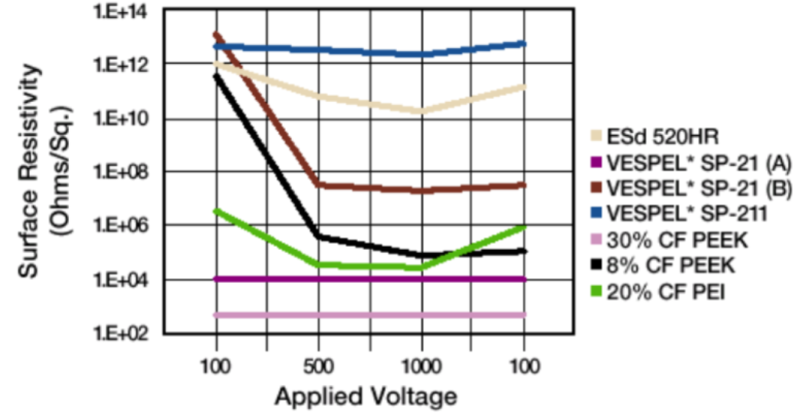
It is important to know how applied voltage affects the resistance of a material. Some materials exhibit high resistance at low voltages, but when subjected to harsher conditions, they can fall. This is due to dielectric breakdown and is irreversible. This chart illustrates the effect of sequential applications of 100 through 1,000 volts, then a return to 100 volts to determine the hysteresis. Since static electricity can be several thousand volts, consistent performance across the voltage range must be considered.
Some materials are very inconsistent and vary on the "grain" of machining. One pair of lines illustrate the typical variation from side to side (A to B) of the same sample. This example demonstrates the need for consistent behavior in service.
- Note
- Thermal Properties - The figures given for these properties are for the most part derived from raw material supplier data and other publications.
- (2) Values for this property are only given here for amorphous materials and for materials that do not show a melting temperature (PBI, PAI & PI). DMA settings, oscillation amplitude of 0.20 mm; a frequency of 1 Hz; heating rate of 2°C/min
- (3) Temperature resistance over a period of min. 20,000 hours. After this period of time, there is a decrease in tensile strength – measured at 23 °C – of about 50 % as compared with the original value. The temperature value given here is thus based on the thermal-oxidative degradation which takes place and causes a reduction in properties. Note, however, that the maximum allowable service temperature depends in many cases essentially on the duration and the magnitude of the mechanical stresses to which the material is subjected.
- (4) Impact strength decreasing with decreasing temperature, the minimum allowable service temperature is practically mainly determined by the extent to which the material is subjected to impact. The value given here is based on unfavorable impact conditions and may consequently not be considered as being the absolute practical limit.
- (5) These estimated ratings, derived from raw material supplier data and other publications, are not intended to reflect hazards presented by the material under actual fire conditions. There is no ‘UL File Number’ available for these stock shapes.
- Mechanical Properties - Most of the figures given for the mechanical properties are average values of tests run on dry test specimens machined out of rods 40-60 mm when available, else out of plate 10-20mm. All tests are done at room temperature (23° / 73°F)
- (7) Test speed: either 5 mm/min or 50 mm/min [chosen acc. to ISO 10350-1 as a function of the ductile behavior of the material (tough or brittle)] using type 1B tensile bars
- (8) Test speed: either 0.2"/min or 2"/min or [chosen as a function of the ductile behavior of the material (brittle or tough)] using Type 1 tensile bars
- (9) Test speed: 1 mm/min, using type 1B tensile bars
- (10) Test specimens: cylinders Ø 8 mm x 16 mm, test speed 1 mm/min
- (11) Test specimens: cylinders Ø 0.5" x 1", or square 0.5" x 1", test speed 0.05"/min
- (12) Test specimens: bars 4 mm (thickness) x 10 mm x 80 mm; test speed: 2 mm/min; span: 64 mm.
- (13) Test specimens: bars 0.25" (thickness) x 0.5" x 5"; test speed: 0.11"/min; span: 4"
- (14) Measured on 10 mm, 0.4" thick test specimens.
- (15) Electrode configuration: Ø 25 / Ø 75 mm coaxial cylinders; in transformer oil according to IEC 60296 ; 1 mm thick test specimens.
- (16) Measured on disks Ø 50 mm x 3 mm.
- (17) Measured on 1/8" thick x 2" diameter or square
- (18) Test procedure similar to Test Method A: “Pin-on-disk” as described in ISO 7148-2, Load 3MPa, sliding velocity= 0,33 m/s, mating plate steel Ra= 0.7-0.9 μm, tested at 23°C, 50%RH.
- (19) Test using journal bearing system, 200 hrs, 118 ft/min, 42 PSI, steel shaft roughness 16±2 RMS micro inches with Hardness Brinell of 180-200
- (20) Test using Plastic Thrust Washer rotating against steel, 20 ft/min and 250 PSI, Stationary steel washer roughness 16±2 RMS micro inches with Rockwell C 20-24
- (21) Test using Plastic Thrust Washer rotating against steel, Step by step increase pressure, Test ends when plastic begins to deform or if temperature increases to 300°F.