
Knowde Enhanced TDS
Identification & Functionality
- Additives Included
- Chemical Family
- Fillers Included
- Polymer Name
- Plastics & Elastomers Functions
- Technologies
Features & Benefits
- Materials Features
- Wear and Friction Solutions High Temperature Materials
Design engineer look to replace metal parts and components with thermoplastics whenever possible. Not only can they be produced more cost-effectively, they offer greater design flexibility, weigh less and resist corrosion. The availability of high temperature resins like PEEK, PPS, PPA and PEI can stretch the use of thermoplastic even further.
If you can’t stand the heat… internally lubricated compounds: While auto under-the-hood and industrial machinery might be the first to come to mind, high temperature application are not always driven by hot operating environment. Some application that may never see elevated use temperatures have to survive a hot manufacturing environment (lead-free solder, paint ovens). High temperature generally feature good chemical resistance as well.
Internally lubricated compounds:
The addition of an internal lubricant to a thermoplastic material can improve the wear resistance and can reduce the coefficient of friction in plastic parts. Traditional lubricants like PTFE and PTFE/Si blends are common. Compounds made with high temperature resins can provide wear performance comparable with externally lubricated metal parts.
- Product Features
- FM: 10.3 GPa
- HDT: 335°C
- Chemical resistance
- Superior bearing performance
- UL94-V0@0.720mm
Applications & Uses
- Markets
- Applications
- Plastics & Elastomers End Uses
- Plastics & Elastomers Processing Methods
Properties
- Flame Rating
- Mechanical Properties
- Physical Properties
- Thermal Properties
- Impact Properties
- Injection Molding
- Flame Characteristics
- Note
- ᵍ Measurements made from Laboratory test Coupon. Actual shrinkage may vary outside of range due to differences in processing conditions, equipment, part geometry and tool design. It is recommended that mold shrinkage studies be performed with surrogate or legacy tooling prior to cutting tools for new molded article.
- ⁷ Injection Molding parameters are only mentioned as general guidelines. These may not apply or may need adjustment in specific situations such as low shot sizes, large part molding, thin wall molding and gas-assist molding.
- ¹¹ The information stated on Technical Datasheets should be used as indicative only for material selection purposes and not be utilized as specification or used for part or tool design.
- ᵖ UL ratings shown on the technical datasheet might not cover the full range of thicknesses and colors. For details, please see the UL Yellow Card.
| Value | Units | Test Method / Conditions | |
| Tensile Stress (Break) ¹¹ | 139 | MPa | ASTM D638 |
| Tensile Stress (Yield, 5 mm/min) ¹¹ | 148 | MPa | ISO 527 |
| Tensile Stress (Yield, Type I, 5 mm/min) ¹¹ | 161 | MPa | ASTM D638 |
| Tensile Strain (Break) ¹¹ | 2 | % | ASTM D638 |
| Tensile Stress (Break, 5 mm/min) ¹¹ | 160 | MPa | ISO 527 |
| Tensile Stress (Break, 5 mm/min) ¹¹ | 148 | MPa | ISO 527 |
| Tensile Stress (Break, Type I, 5 mm/min) ¹¹ | 159 | MPa | ASTM D638 |
| Tensile Modulus (at 50 mm/min) ¹¹ | 11030 | MPa | ASTM D638 |
| Tensile Strain (Break, Type I, 5 mm/min) ¹¹ | 2.1 | % | ASTM D638 |
| Tensile Strain (Yield, 5 mm/min) ¹¹ | 2.8 | % | ISO 527 |
| Flexural Stress ¹¹ | 206 | MPa | ASTM D790 |
| Flexural Stress ¹¹ | 229 | MPa | ISO 178 |
| Tensile Modulus (at 5 mm/min) ¹¹ | 12360 | MPa | ASTM D638 |
| Tensile Strain (Break, 5 mm/min) ¹¹ | 2.1 | % | ISO 527 |
| Tensile Strain (Break, 5 mm/min) ¹¹ | 2.9 | % | ISO 527 |
| Flexural Modulus ¹¹ | 10340 | MPa | ASTM D790 |
| Flexural Stress (Break, 1.3 mm/min, 50 mm span) ¹¹ | 239 | MPa | ASTM D790 |
| Tensile Modulus (at 1 mm/min) ¹¹ | 11840 | MPa | ISO 527 |
| Flexural Modulus (at 1.3 mm/min, 50 mm span) ¹¹ | 10300 | MPa | ASTM D790 |
| Flexural Stress (Yield, at 2 mm/min) ¹¹ | 211 | MPa | ISO 178 |
| Flexural Stress (Break, 2 mm/min) ¹¹ | 210 | MPa | ISO 178 |
| Flexural Strain (Break, at 2 mm/min) ¹¹ | 3.3 | % | ISO 178 |
| Flexural Modulus (at 2 mm/min) ¹¹ | 9700 | MPa | ISO 178 |
| Flexural Modulus (at 2 mm/min) ¹¹ | 10320 | MPa | ISO 178 |
| Value | Units | Test Method / Conditions | |
| Density ¹¹ | 1.43 | g/cm³ | ISO 1183 |
| Density ¹¹ | 1.43 | g/cm³ | ASTM D792 |
| Wear Factor Washer ¹¹ | 16 | 10^-10 in^5-min/ft-lb-hr | ASTM D3702 Modified: Manual |
| Wear Factor Washer ¹¹ | 12 | 10^-10 in^5-min/ft-lb-hr | ASTM D3702 Modified: Manual |
| Wear Factor Washer ¹¹ | 10 | 10^-10 in^5-min/ft-lb-hr | ASTM D3702 Modified: Instr. |
| Dynamic COF ¹¹ | 0.35 | — | ASTM D3702 Modified: Manual |
| Dynamic COF ¹¹ | 0.28 | — | ASTM D3702 Modified: Instr. |
| Static COF ¹¹ | 0.23 | — | ASTM D3702 Modified: Manual |
| Static COF ¹¹ | 0.42 | — | ASTM D3702 Modified: Manual |
| Static COF ¹¹ | 0.56 | — | ASTM D3702 Modified: Instr. |
| Mold Shrinkage (flow) ᵍ ¹¹ | 0.1 - 0.2 | % | SABIC method |
| Water Absorption (at 23°C, 24hrs) ¹¹ | 0.09 | % | ISO 62-1 |
| Specific Gravity ¹¹ | 1.43 | — | ASTM D792 |
| Moisture Absorption (at 23°C, 50% RH, 24hrs) ¹¹ | 0.05 | % | ASTM D570 |
| Mold Shrinkage (flow, 24 hrs) ᵍ ¹¹ | 0.4 - 0.6 | % | ASTM D955 |
| Mold Shrinkage (xflow, 24 hrs) ᵍ ¹¹ | 0.7 - 0.9 | % | ASTM D955 |
| Wear Factor Ring ¹¹ | 2 | 10^-10 in^5-min/ft-lb-hr | ASTM D3702 Modified: Manual |
| Moisture Absorption (at 23°C, 50% RH) ¹¹ | 0.08 | % | ISO 62 |
| Value | Units | Test Method / Conditions | |
| Heat Deflection Temperature (at 1.82 MPa, 3.2mm, Unannealed) ¹¹ | 290 | °C | ASTM D648 |
| Heat Deflection Temperature (at 1.82 MPa, 3.2mm, Unannealed) ¹¹ | 322 | °C | ASTM D648 |
| Coefficient of Thermal Expansion (at 23°C to 60°C, flow) ¹¹ | 0.000044 | 1/°C | ISO 11359-2 |
| Coefficient of Thermal Expansion (at 23°C to 60°C, xflow) ¹¹ | 0.000048 | 1/°C | ISO 11359-2 |
| Heat Deflection Temperature/Bf (at 0.45 Mpa, Flatw 80*10*4, sp=64mm) ¹¹ | min. 300 | °C | ISO 75/Bf |
| Heat Deflection Temperature/Bf (at 0.45 Mpa, Flatw 80*10*4, sp=64mm) ¹¹ | 335 | °C | ISO 75/Bf |
| Heat Deflection Temperature/Af (at 1.8 Mpa, Flatw 80*10*4, sp=64mm) ¹¹ | min. 300 | °C | ISO 75/Af |
| Heat Deflection Temperature/Af (at 1.8 Mpa, Flatw 80*10*4, sp=64mm) ¹¹ | 335 | °C | ISO 75/Af |
| Heat Deflection Temperature (at 0.45 MPa, 3.2 mm, Unannealed) ¹¹ | 336 | °C | ASTM D648 |
| Coefficient of Thermal Expansion (at -30°C to 30°C, flow) ¹¹ | 0.000018 | 1/°C | ASTM D696 |
| Coefficient of Thermal Expansion (at -30°C to 30°C, xflow) ¹¹ | 0.000042 | 1/°C | ASTM D696 |
| Value | Units | Test Method / Conditions | |
| Izod Impact (Unnotched, at 23°C) ¹¹ | 480 | J/m | ASTM D4812 |
| Izod Impact (Notched, at 23°C) ¹¹ | 58 | J/m | ASTM D256 |
| Izod Impact (Unnotched, 80*10*4, at 23°C) ¹¹ | 40 | kJ/m² | ISO 180/1U |
| Izod Impact (Unnotched, 80*10*4, at 23°C) ¹¹ | 30 | kJ/m² | ISO 180/1U |
| Izod Impact (Notched, 80*10*4, at 23°C) ¹¹ | 8 | kJ/m² | ISO 180/1A |
| Izod Impact (Notched, 80*10*4, at 23°C) ¹¹ | 5 | kJ/m² | ISO 180/1A |
| Multi-Axial Impact ¹¹ | 2 | J | ISO 6603 |
| Instrumented Dart Impact Total Energy (at 23°C) ¹¹ | 7 | J | ASTM D3763 |
| Value | Units | Test Method / Conditions | |
| Drying Temperature ⁷ | 150 | °C | — |
| Drying Time ⁷ | 4 - 6 | Hrs | — |
| Front - Zone 3 Temperature ⁷ | 380 - 400 | °C | — |
| Middle - Zone 2 Temperature ⁷ | 380 - 400 | °C | — |
| Rear - Zone 1 Temperature ⁷ | 370 - 380 | °C | — |
| Mold Temperature ⁷ | 175 - 190 | °C | — |
| Back Pressure ⁷ | 0.3 - 0.7 | MPa | — |
| Screw Speed ⁷ | 60 - 100 | rpm | — |
| Value | Units | Test Method / Conditions | |
| UL Recognized (94V-0 Flame Class Rating) ᵖ | 0.72 | mm | UL 94 |
Regulatory & Compliance
- Certifications & Compliance
Technical Details & Test Data
- LNP™ Compounds Wear and Friction Solutions Bearings, Bushings, Cams and Sliders
At the push of a button, windows move, doors lock, copies get made, and HVAC comes to life. These electromotive actions require gears, bearings, bushings and other wear surfaces to provide smooth, reliable, actuation forces. LUBRICOMP™ and LUBRILOY™ compounds can help deliver the high quality performance required.
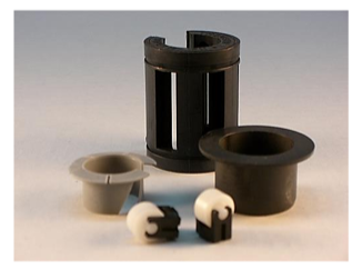
Thermoplastic Bearings
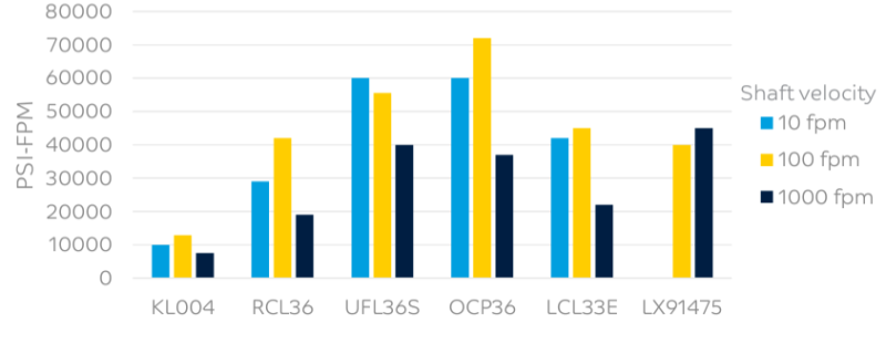
While resistance to wear is important for thermoplastic bushings/bearings, low friction can be more important. Heat generated from friction is often the limiting factor in plastic bearing applications. The operating load (P) and speed (V) of the application can be compared to the allowable, or “Limiting PV” of a candidate material. The data shown below was generated using a cylindrical half bearing test configuration, but modern thrust washer testers can be used to develop PV maps as well.
Internally Lubricated Compounds
The addition of an internal lubricant to a thermoplastic material can improve the wear resistance and reduce the coefficient of friction in plastic parts. Traditional lubricants like MoS2 , PTFE and PTFE/Si blends are common, with reinforcements like glass and carbon fiber adding strength and modulus. High temperature resins are sometimes required to resist deformation from friction generated heat.
Limiting Pressure Velocity
Packaging & Availability
- Regional Availability